
Constructing the Roadbed
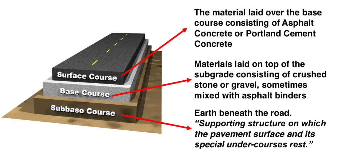
Roadway has three major structural parts:
Construction and Maintenance Requirements of Untreated Gravel Road Surface
Road must be stable to support the super imposed loads without detrimental deformation.
Must shed a large portion of rain that falls on the surface because water penetrating the sub grade might soften it and loosen the surface stability.
Must be from large rocks or stones over one inch in diameter for maintenance.
Must possess capillarity properties sufficient enough to replace the moisture lost through the surface evaporation.
On dry weather, moisture film on the clay particles should bind the entire mass together, and in wet weather, first rain the falls should expand the clay and close the pores to prevent water from entering and softening the materials.
1. Cut off a thin layer of the road surface using road grader distributing the scraped layer uniformly over the roadway surface.
Blading sequence is done once or twice a year, sometimes monthly. After blading, compact road using road roller.
Effective routine maintenance is done after rainfall where surface is still soft to blade.
Pavement Maintenance Structure Techniques: https://www.youtube.com/watch?v=kysDqbO99N4
AASHTO standard specifications requires maximum liquid limit of 35 and a Plastic Index of 4 to 0 and a maximum 8% passing the No. 200 sieve.
Treated Base Course
Type of asphalt binders for base course depends on several factors:
1. Quality of asphalt is classified as either for stabilizing or for waterproofing purposes only.
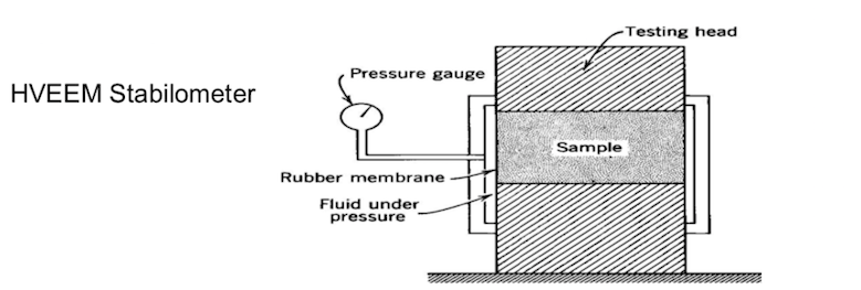
2. If purpose is for stability, test with Marshall or HVEEM Stabilometer. Weight of asphalt in percentage should range between 5%-7%.
3. If purpose is waterproofing, 2% – 3% of the asphalt binder is added.
4. If emulsion asphalt is used, enough water is included in the mixture to allow compaction at near optimum moisture content.
Type of asphalt binders for base course depends on several factors:
Tutorial: Marshall Stability Test
https://www.youtube.com/watch?v=M1vKNrcRtbU
Sand and Asphalt Base Course
Sand and Asphalt Base Course
Asphalt binders for hot plant mixing should be:
a) medium viscosity, rapid or medium curing asphalts, b) slow setting emulsified asphalt or
c) tars of grade RT-6 to RT-10.
The content of asphalt binder is in percent by weight ranging from 4% to 10%. Compaction is done using either pneumatic tired or smooth wheeled roller.
Fine Grain Asphalt Base
An asphalt stabilized base constructed with fine grain has a controlled Plastic Index of 6 to 10 respectively. Aggregates with PI up to 30 are processed with lime. Those with up to 50% passing the No. 200 sieve and PI up to 18 can be stabilized even without pre-treatment.
Soil and Base Course Stabilized with Cement
Cement stabilized base course is less susceptible to deformation caused by moisture and temperature changes.
Though this is less rigid than the Portland cement concrete because of high modulus of elasticity (ranges from 100,000 for clay soils with little cement, up to 1,000,000 for strong mix).
Portland cement modulus of elasticity ranges from 3 to 6 million with compressive strength of 3,000 to 5,000 psi.
Soil cement is subdivided into three types:
1. Sandy and gravelly containing less than 25% silt and clay
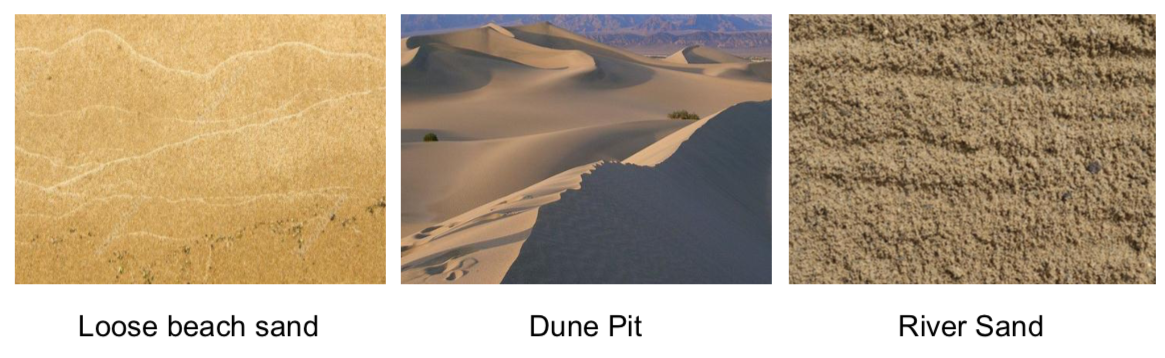
2. Sandy with lesser amount of fines like beach sand
3. Silty and Clayey soils
The quality of aggregate cement mixture is measured by its ability to resist abrasion and disintegration.
See: Unconfined and Triaxial Compression and Flexure Tests
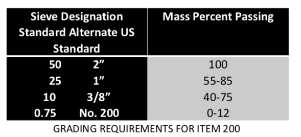
DPWH Standard Specifications on Aggregate Sub-Base Course
Conditions
The fraction passing the 0.75 mm sieve should not be greater than 0.666 (2/3) of the fraction passing the 0.425 mm No. 40 sieve.
Fraction passing the 0.425 mm sieve should have a liquid limit not greater than 35 and PI not more than 12 as determined by AASHTO T-89 and T-90 respectively.
The coarse portion retained on a 3 mm sieve shall have a mass percent of wear not to exceed 50 by the Los Angeles Abrasion Tests as determined by AASHTO T-193. CBR value is obtained at max density as determined by AASHTO T-180 Method D.
Construction Requirements and Equipment
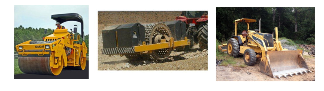
Tamping rollers, grid rollers, pneumatic tire rollers, smooth tire rollers, vibratory compactor, hauling and spreading equipment are used in constructing the roadbed.
Preparation of the Soil Aggregate
Case 1: For new soil aggregate
Existing roadbed is scarified lightly and bladed to a uniform grade. Roll, water and roll again.
Depressions appearing on the surface are filled and the weak portion of the roadbed is strengthened with new soil aggregate.
Allow one day for measuring, sampling, and testing of the sample for approval of the quality and gradation before spreading the windrow for application of the hydrated lime.
If soil aggregate moisture exceeds two mass percent of the dry aggregate, apply aeration by harrowing the soil aggregate until the moisture content is reduce to 2% or less.
Spread the aggregate smoothly and uniformly over half the road ready for the application of hydrated lime.
Case 2: For Salvage soil aggregate
Surface should be scarified lightly and bladed to uniform grade.
Reshaped surface is scarified again to depth required leaving a foundation of undisturbed material parallel with cross section.
Loosened materials are bladed into a windrow at the side of the roadway. Undisturbed materials are rolled, watered and rolled again.
Application of Lime
Hydrated lime is uniformly spreaded at specified percent using either the dry or slurry (wet) methods.
The lime is distributed in successive applications at the amount and intervals as prescribed.
Immediately after the distributor, after each application partially mix the lime with the soil aggregate.
Dry application is either by spotting bags of lime in equal pre-determined intervals or by applying in bulk from trucks.
If slurry lime is employed, the typical slurry ratio is 1,000 kg lime to 2 cm3 water. The actual mixing proportion depends upon percent of lime specified, type of soil and its moisture condition.
To prevent run-off and consequent non-uniformity of lime distribution, the slurry is mixed immediately after each spreading pass.
Mixing
1. Following the last lime application and partial mixing, the entire mass of mixture is withdrawn on the road surface and then mixed by blading the mixture from side to side of the road until whole mass has uniform color. MUST BE FREE OF LEAN SPOTS OR BALLS OF UNMIXED PARTICLES.
2. If there is an excess of deficiency or uneven distribution of lime, condition must be corrected by adding soil aggregate or lime then remix.
3. For mixtures with excessive amount of water or volatile matter, mixtures should be bladed, aerated or manipulated until the moisture and volatile content becomes satisfactory.
4. Whether mixing is completed or not, all loosened materials are bladed into a windrow at the end of each work day.
Spreading, Compacting and Finishing
Materials are spreaded by self-propelled pneumatic tired blade grader or mechanical spreader. Cutting underlying course should be avoided.
After spreading, surface is leveled to the road center line then to the outer edges of the road.
Each pass should terminate at least 90 cm in advance.
During the time of compaction, surface is dragged or bladed as necessary to fill and remove the incipient corrugation or other surface irregularities.
Continue rolling until texture is satisfactorily compacted. Stop if there is excessive pulverizing of the aggregate.
Road Mix
Portland Cement Stabilized Road Mix Base Course (Item 204)
Amount of cement added to the aggregate shall be 6 to 10 mass percent of the dry aggregate.
Construction requirement and procedures is the same as that of Item-203. Replace lime with Portland Cement
Asphalt Stabilized Road Mix Base Course (Item 205)
• Amount of asphalt material to be added to the aggregate should be from 4 to 7 mass percent of the dry aggregate.
Portland Cement Treated Plant Mix Base Course (Item 206)
• Travel Plant Mixing Method
Aggregates to be treated is placed in uniform windrow spreaded to a uniform thickness to the required depth.
Portland cement is applied uniformly in a trench on top of the windrows or spreaded uniformly over aggregates.
Mixing is done by machine.
Max of 2 hours is allowed for wet mixing, letdown and finishing.
Portland Cement Treated Plant Mix Base Course (Item 206)
Central Plant Mixing Method
Plant is equipped with feeding and metering devices that will introduce the cement aggregate and water into the mixer in quantities specified. Continue mixing until a uniform mixture is attained.Spreading, Compacting and Finishing
Not more than 60 minutes should elapse from the start of mixing to compaction of the laid mixture. After spreading, compact mixture and finished with same procedure as lime stabilized road mix.
Subgrade Preparation
All materials below the sub-grade is leveled to a depth of 15 cm or more as specified to meet the requirements of selected borrow toppings.
Everything should be compacted prior to the preparation of sub-grade.
Sub-grade Level Tolerance
Permitted variance from design +20 mm
Level of Service . – 30 mm
Permitted surface irregularities measured by 3m straight edge ±30mm
Permitted variance from design cross-fall of camber 0.5%
Permitted variance from design longitudinal grade over 25 m long ±0.1%
Concrete Pavement
Portland Cement
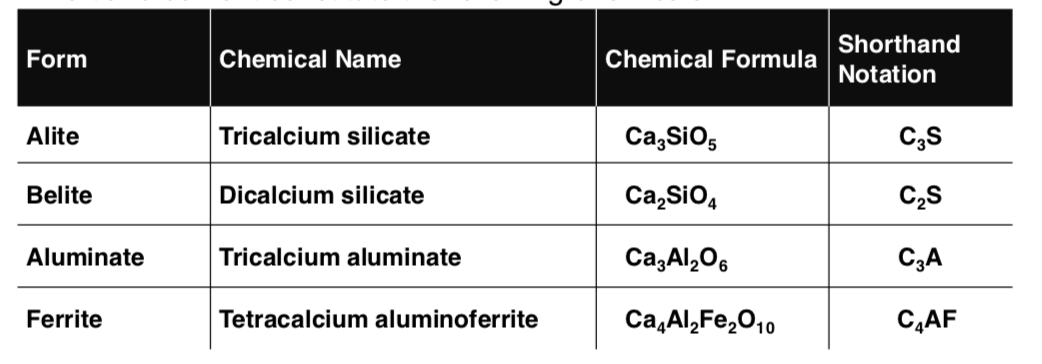
Portland cement is a combination of limestone, marl or other calcareous materials and clay, shale, or like argillaceous substances.
Portland cement constitute the following chemicals:
Concrete Pavement Characteristics and Behavior
Behavior of concrete pavement that is exposed to loading and environmental effect entirely depends upon:
The quality of concrete
The underlying sub grade
And the base course.
Concrete is strong in resisting compression but considerably weak in resisting tensile stresses. It also reacts to temperature changes expanding when wet and contracting when dried.
Pavement design assumes the following considerations:
1. Transverse cracks on concrete pavement cannot be avoided.
Pavement cracks can be controlled through:
• Reinforcement
• Aggregate interlock or dowel bars • Steel between joints
2. Longitudinal cracks more than 1 lane wide cannot be prevented.
3. Pavement slab is supported by foundation that deflects when loaded but recover when the load is removed.
Distress of Concrete
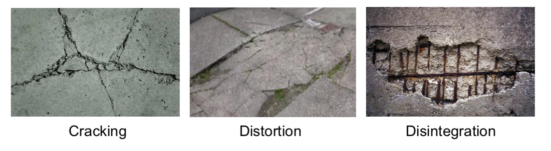
Distortion
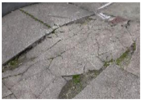
Vertical displacement of concrete slab at the joints or cracks. It is due to failure or weakness of concrete joints.
Cracking
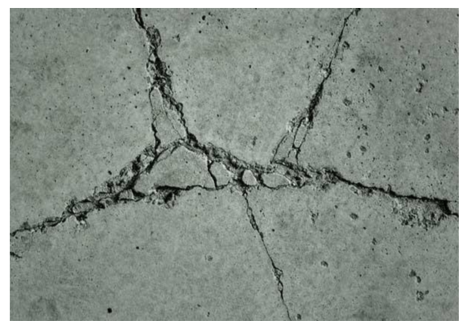
Can take many forms in concrete pavement that could be the result from:
• Applied load
• Temperature
• Moisture changes
The most common types of cracks are:
Corner cracks with excessive corner deflection
Transverse cracks associated with mixture or temperature stresses, or poor construction methods.
Disintegration
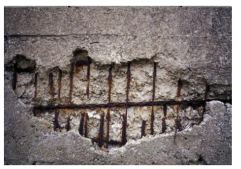
Appears in the form of durability cracking, scaling or spalling as the result of mix design or construction related problems like:
Durability Cracking – Results from freeze – thaw action
Scaling – a network of shallow fine hairline cracks which exctend through the upper surface of concrete. This is the result from the deicing salts, improper construction, freeze – thaw cycle, or steel reinforcement too close to the surface.
Spalling – breaking or chipping of the joint edges. It is the results from excessive stresses at joint, weak concrete, poorly designed or constructed joints.
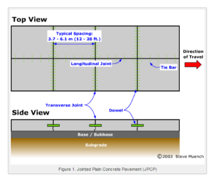
Concrete Joints
Transverse Expansion Joints: provide space allowance for the lengthening of slab due to expansion.
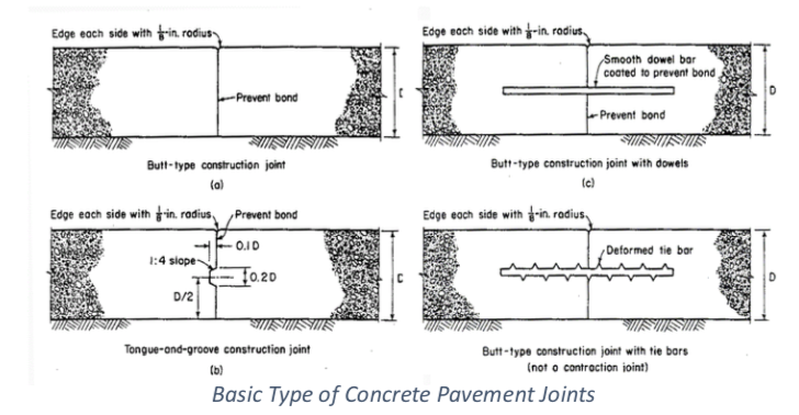
Longitudinal Joints: provided between adjacent traffic lanes. Provides edge support as hinges but allows rotation between the slabs.
Formula for designing steel bar used for reinforcement of a concrete slab is:
?? = ??? / 2?
Where:
As – Area of steel cross section per foot of slab
L – Length of Slab Between Joints in Feet
f – Coefficient of friction between the slab and the subgrade (check AASHTO Interim Guide) S – Working stress in the reinforcing stein in lbs per sq. in. (Check AASHTO Interim Guide)
Welded wire fabrics are also used as reinforcement for concrete pavement made from cold drawn steel wires having the following properties.
• Min. Allowed Tensile Strength: 80,000 psi
• Yield Strength: 70,000 psi
• Reinforcing bars steel yield strength: 40,000 to 75,000 psi
Concrete Proportions
The fundamental rule to obtain good concrete is the proper selection of cement aggregate and water thus:
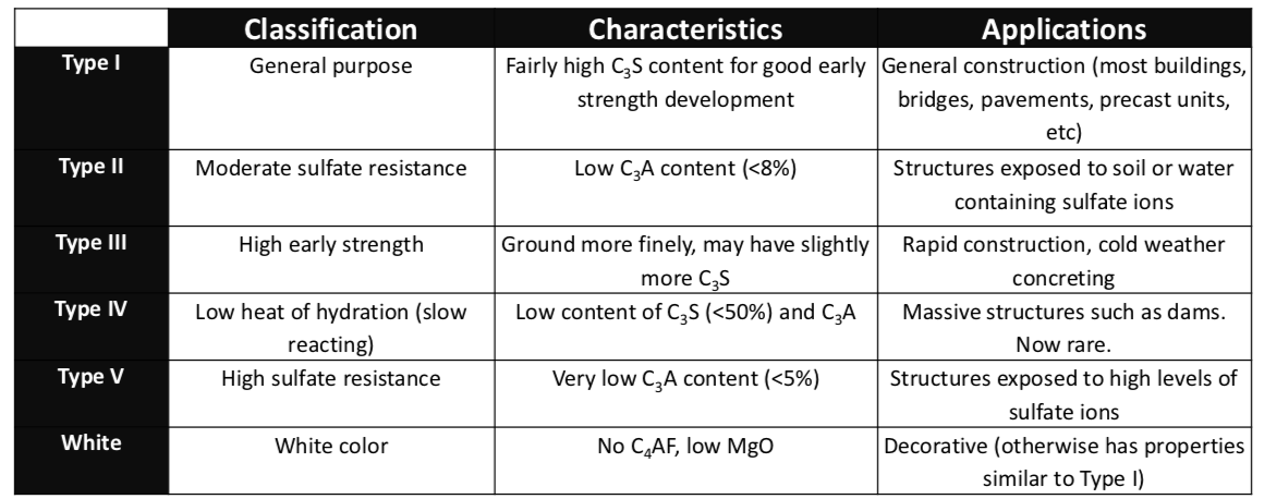
1. Type I or II is specified for concrete pavement.
Water for concrete must be clean, free from acids, alkali, and oil.
The mineral aggregate of concrete is about 75% of the volume or about 80% of the weight of normal pavement.
Max size of coarse aggregates is 2 in. There are instances however that the use of larger aggregates increases its length and durability.
Admixture
Admixture is a substance added in mixing to change the characteristic of concrete mixture. Examples of admixtures available are air-entraining admixture, water reducer, retarder, accelerator, pozzolan, and plasticizer.
Purpose of air-entrainment is to increase the durability of concrete. Increasing the durability is influenced by:
1. Percentage of air present in the mixture.
2. Grading of Aggregates
3. Size and distribution of air bubbles
Cement and Water Ratio
A non air-contrained concrete with a water cement ratio by weight of 5 gallons of water per bag of cement may have a compressive strength of about 5,300 psi in 28 days. A mixture of concrete with 7 gallons of water per bag of cement has developed strength 3,700 psi only for 28 days.
AASHTO Guide Specifications for highway construction (also: https://www.transportation.alberta.ca/Content/docType245/Production/Specs2007.pdf) establishes max water cement ratio at 6 gallons per bag of cement on normal conditions and 5 1⁄2 gallons per bag of cement for severe atmospheric conditions.
Concrete Mixture
Objective is to use more aggregates and as little cement as possible while maintaining workability necessary for successful pouring and consolidation.
Reducing the amount of cement-water paste and the cost of the mixture:
• Allow larger size of aggregate that can be accommodated in the pavement slab.
• Aggregate should be uniformly graded from coarse to fine.
•Get the biggest quality of coarse aggregate consistent with proper workability.
• Adopt the lowest slump consistent with the proper pouring and finishing. (specified value of slump is 1-2 or 2-3 inches)
Slump Test
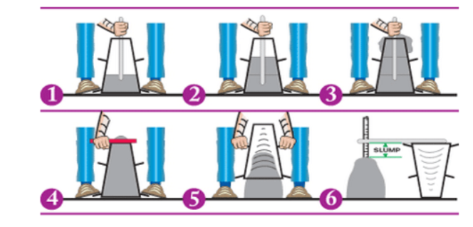
SLUMP TEST (AASHTO T-119)
Old traditional and most widely used method in determining the consistency of concrete. A truncated cone of metal sheet is filled with fresh concrete. Cone is then lifted off vertically allowing concrete to subside.
Kelly Ball Method and Trial Batch
Kelly ball method (ASTM C-360) is another way of testing consistency of concrete. https://www.youtube.com/watch?v=eWO-HmfC-uY
Advantage of Kelly Ball is that reading could be taken immediately on the concrete being poured on the roadway. On the contrary, slump test requires more time but could be conducted only on selected samples.
Concrete mixture is determined by the trial batch method, until after the desired mixture is obtained as final proportion for the succeeding mixture.
Curing of Concrete Pavement
Keep surface constantly wet or cover it with water absorbent materials that is re-wetted from time to time. If the concrete dries out quickly, hydration and strength process will stop, but when moisture becomes available during hydration, strength gain will continue.
Rapid drying of fresh concrete will result to surface crazing or cracking. Shortest period of curing for normal concrete is 5 days per AASHTO recommendation.
DPWH Specifications on Concrete Pavement
Also check: https://dpwhaccreditedme.blogspot.com/2017/04/item-311- portland-cement-concrete.html
Only type I Portland cement should be used. Different brands or the same brands from different mills shall not be mixed nor shall they be used alternately unless approved by the supervising engineer.
Cement that for any reasons become partially hardened, or which contains lumps or caked cement including those salvaged from discarded or used bags, should not be used.
Fine Aggregates
Fine aggregate shall consist of natural sand, stone screening or other inert materials with similar characteristics having strong durable particles.
Fine aggregates from different sources should not be mixed or stored in the same pile nor used alternately.
FA should not contain more than 3 mass percent of materials passing the 0.075 mm (No. 200 sieve) by washing nor more than one mass percent each of clay lumps or shale.
Use of beach sand will not be allowed without approval of supervising engineer.
If the fine aggregate is subjected to 5 cycles of the Sodium Sulfate Soundness Test (also see: https://www.pavementinteractive.org/durability-and-soundness/), weighed loss should not exceed 10 mass percent.
If fine aggregate is subjected to test for organic impurities and a color darker than the standard is produced, it should be rejected. Also check using AASHTO T-71, if checked, fine aggregate may be used if the relative strength at 7 and 28 days is not less than 95 mass percent.
Coarse Aggregates
1. Coarse aggregate shall consist of crushed stone, gravel, blast furnace, slag or other approved inert materials with similar characteristics having strong durable particles free from adherent coatings.
2. CA should not contain more than 1 mass percent of materials passing the 0.075 mm (No. 200 sieve) nor more than 0.25 mass percent of clay lumps, not more than 3.5 mass percent of soft fragments.
3. If the coarse aggregate is subjected to 5 cycles of the Sodium Sulfate Soundness Test (also see: https://www.pavementinteractive.org/durability-and-soundness/), weighed loss should not exceed 12 mass percent. Should have percent of wear not exceeding 40 when tested by AASHTO T-96.
4. If slag is used its density should not be less than 1120 kg per cubic meter.
Proportioning, Consistency and Strength of Concrete
Prepare a design mixture based on the absolute volume method as specified in the American Concrete Institute (ACI) standard. For the ACI Method check: https://civildigital.com/aci-method/.
Require 9 bags of cement per cubic meter of concrete based on a 40 kg weight per bag of cement. You can use leaner or richer mixture to meet minimum strength requirements.
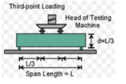
Slump should be between 40-70 mm if not vibrated or between 10-40 mm if vibrated and flexural strength of not less than 3.8 Mpa when tested by the third-point method or a compressive strength of 24.1 Mpa (3,500 psi) when tested at 14 days.
For three point method check: https://edge.rit.edu/edge/P14416/public/FinalDocuments/Flexural%20Test%20Procedure.pdf
For three point method check: https://edge.rit.edu/edge/P14416/public/FinalDocuments/Flexural%20Test%20Procedure.pdf
Handling, Measuring, and Batching of Materials
Mixing Concrete
Ready mix concrete shall be mixed and delivered in accordance with AASHTO M-157 requirements, except that the minimum required revolutions at the mixing speed for transit mixed concrete may be reduced to not less than that recommended by the mixer manufacturer. (no. of revs. Should be indicated on a serial plate attached to the mixer)
If mixing done in the site or central mixing plant, mixing time should not be less than 50s nor more than 90s, unless mixing performance tests provide adequate mixing of the concrete in a shorter time period.
The volume of the concrete mix per batch should not exceed the mixers nominal capacity in cubic meter as indicated on the manufacturers standard rating plate attached on the mixer except that an overload up to 10% above the mixers normal capacity may be permitted.
Batches shall be charged into the drum with a portion of the mixing water enter in advance of the cement and aggregates.
Throat of the drum shall be kept free of concrete accumulation that may restrict the free flow of materials into the drum.
Time elapsed from the time water is added to the mix until the concrete is deposited in place at the site shall not exceed 45 minutes (non-agitating trucks) nor 90 minutes (truck agitators).
Re-tampering concrete is not allowed except when concrete is delivered in truck mixers (additional water and additional mixing) to meet specifications so long as it is within 45 minutes after the initial mixing operations and the water cement ratio is not exceeded.
Placing and Finishing of Concrete
Check presentation from Portland Cement Association: www.mse.mtu.edu/~llsutter/classes/cet1141/present/finishin.ppt
Acceptance of Concrete
The strength level of concrete will be considered satisfactory if the average of all sets of 3 consecutive strength test results equal or exceed the specified strength f’c and no individual strength test result is deficient by more than 15% of the specified f’c.
Concrete that does not satisfy the above criteria, may be rejected unless the contractor could provide evidence, by means of core tests that the quality of concrete presented by the failed test result is acceptable in place.
AT least 3 representative cores are taken from each member of concrete area in place that is considered deficient. The obtaining and testing of drilled cores shall be in accordance with AASHTO T-24 requirements. Concrete in the area represented by the core will be considered adequate if the average strength of the cores is equal to at least 85% of f’c and if no single core is less than 75% of the specified strength.

![]()
![]()


